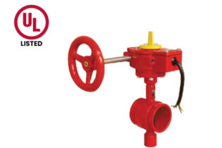
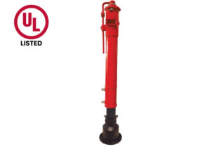
Installation instructions:
- Unload the upper cover of control lead
- Measure control lead depth. Remove the excess part of connector lead and driving rod
- Fit the control rod with full closed valve.turn the position plate to SHUT position
- Load upper Cover
| 22 | Keyhole Plate Gasket | 2 | EPDM | ASTM D2000 | |||
| 21 | Keyhole | 2 | Organic glass | ||||
| 20 | Keyhole Plate | 2 | A283 Gr.c | ASTMA36 | |||
| 19 | Bolt, Flat Gasket | 4 | S.S.304 | ASTM A276 | |||
| 18 | Screwed Plug | 1035 | ASTM A449 | ||||
| 17 | Bolt | 2 | 1035 | ASTM A449 | |||
| 16 | Nut | 2 | 1035 | ASTMA449 | |||
| 15 | Screw | 1035 | ASTMA449 | ||||
| 14 | Lift Ring | 1035 | ASTMA449 | ||||
| 13 | Gasket | A283 Gr.c | ASTM A36 | ||||
| 12 | Handwheel | Cl | ASTMA126 | ||||
| 11 | Upper Cover | Cl | ASTM A126 | ||||
| 10 | Retainer Ring For S1em | 1566 | ASTM A29 | ||||
| 09 | Driver | S.S.304 | ASTM A276 | ||||
| 08 | Position Bracket | S.S.304 | ASTM A276 | ||||
| 07 | Stud Bolt | 4 | 1035 | ASTM A449 | |||
| 06 | Nut,Gasket | 4 | 1035 | ASTM A449 | |||
| 05 | Indicator Plate | 4 | A413.0 | ASTM S12A | |||
| 04 | Main Body | Cl | ASTMA126 | ||||
| 03 | Driving Rod | 1045 | ASTMA29 | ||||
| 02 | Cotter Pin | 1035 | ASTMA449 | ||||
| 01 | Joint | Cl | ASTM A126 | ||||
| NO. | Name | Qty. | Material | Remark |